
Alcohol Based Hand Rub Dispenser (ABHR)
Alcohol Based Hand Rub Dispensers (ABHR) are protected in accordance with 8.7.3.1, unless all conditions are met:
- Corridor is at least 6 feet wide
- Maximum individual dispenser capacity is 0.32 gallons (0.53 gallons in suites) of fluid a11d 18 ounces of Level l aerosols
- Dispensers shall have a minimum of 4-foot horizontal spacing
- Not more than an aggregate of l O gallons of fluid or 135 ounces aerosol are used in a single smoke compartment outside a storage cabinet, excluding one individual dispenser per room
- Storage in a single smoke compartment greater than 5 gallons complies with NFPA 30
- Dispensers are not installed within l inch of a11 ignition source
- Dispensers over carpeted floors are in sprinklered smoke compartments
- ABHR does not exceed 95 percent alcohol
- Operation of the dispenser shall comply with the following criteria:
- The dispenser shall not release its contents except when the dispenser is activated, either manually or automatically by touch-free activation.
- Any activation of the dispenser shall occur only when an object is placed within 4 in. (100 mm) of the sensing device.
- An object placed within the activation zone and left in place shall not cause more than one activation.
- The dispenser shall not dispense more solution than the aniount required for hand hygiene consistent with label instructions.
- The dispenser shall be designed, constructed, and operated in a manner that ensures that accidental or malicious activation of the dispensing device is minimized.
- The dispenser shall be tested in accordance with the manufacturer's care and use instructions each time a new refill is installed.
ABT-JR is protected against inappropriate access
Special consideration should be given to the following:
- Obstructions created by the installation of hand-rub solution dispensers
- Location of dispensers with regard to adjacent combustible materials and potential sources of ignition, especially where dispensers are mounted on walls of combustible construction
- Requirements for other fire protection features, including complete automatic sprinkler protection, to be installed throughout the compartment
- Amount and location of the flammable solutions, both in use and in storage, particularly with respect to potential for leakage or failure of the dispenser
Prohibited location for alcohol-based hand-rub dispenser with respect to ignition source.
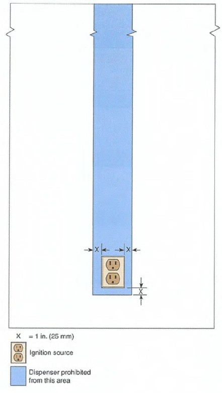
The diagram shows an electrical outlet labeled “ignition source.” A shaded blue area surrounds the outlet, indicating the zone where alcohol‑based hand rub dispensers are prohibited. The prohibited zone extends 1 inch (25 mm) in all directions from the ignition source.
Emergency Preparedness Plan and Training Records
(Located in separate binder in the Safety Training Director Office.)
Fire Plan
GENERAL DIRECTIVES
- All employees are instructed on the fire plan during their initial orientation and through monthly drills. An annual review & update of the Fire Plan is also held.
- Department supervisors are responsible for on-going instructions as needed for their department.
- Each employee is responsible for knowing and following the Fire Plan.
- The primary objective of the Fire Plan is to know what to do if a fire occurs and to prevent fires, injuries, and to save lives.
- Fire alarms are pulled:
- If you smell smoke
- If you see smoke and/or flames
- Know location and use of fire alarms and fire extinguishers.
GENERAL RESPONSIBILITIES FOR ALL EMPLOYEES DURING "RED EVENT"
- Remain calm. Do not shout "Fire".
- Move residents to the safest area, if they are in danger.
- Pull alarm if you are the one discovering the fire.
- Fight Fire with proper equipment if needed and safe to do so.
- Keep visitors with residents, offer reassurance. Stay with residents as assigned.
- Close doors (fire doors close automatically). Turn off oxygen at bedside. Clear halls and exits, (carts and equipment should be moved to empty rooms.)
- Report to supervisor and follow directive given.
- Walk-Do not Run. Keep to the right in halls. Do not crossfire area.
- One person from each department needs to respond to the fire with an extinguisher, if safe to do so.
Remember to R.A.C.E.
R - Rescue - Rescue anyone near area
A - Alarm -Pull fire alarm, report exact location to nurse's station. Announce Red Event and exact location. Report to nurse's station.
C - Contain - Close off area by fire
E - Extinguish - If possible, put out fire with fire extinguisher
GENERAL RESPONSIBILITIES FOR NURSE IN CHARGE
See Chain of Command
- Locate Fire (may ask another to help locate fire) Check closed doors before opening. IF door is HOT, Do Not Open. Check boards at nurse's station to report exact location. Charge nurse checks board when fire alarm goes off *(if actual fire, also give nature of fire,) Nurse in charge will report to scene of fire with an extinguisher.
- Person at Nurse's Station:
- Announce "Red Event" & fire location three times
- *Call fire department (911) and inform exact location of fire, nature of fire & which door to enter (fire department will call•••to confirm any alarms.) Designate someone to direct the fire department personnel when they arrive. (Housekeeping and maintenance)
- *Call to inform Administrator, Maintenance Manager and DON and others as listed in this manual's call list as necessary.
- Assign staff members to stay with residents and visitors in the areas designated until instructed otherwise.
6:00 AM-6:30 PM Shift
All Nurses, CNA's and RN's report to Nurse's Station. Staff report to nurse's station.
6:00 PM - 6:00 AM Shift
*Assign staff member, if available to stay by phone.
*Obtain assistance from off-duty employees reporting to the facility to assist as needed.
*Evaluate the need to evacuate and initiate if needed.
- Announce all Clear. *If actual fire, obtain administrative designee's approval. *Only if actual fire OR Fire Department responds to an alarm.
- After "ALL CLEAR" silence alarm.
- Insert the Hudson Key on the nurse's key ring and tum.
- Push silence on alarm panel.
- To Reset the Alarm:
- If pull station has been pulled: Reset the pull station with the Hudson Key on the nurse's key ring.
- Insert the Hudson Key and turn, Push: Reset Alarm.
- Complete fire report form. Maintenance completes fire report and drill reports or person in charge if maintenance is not present.
OTHER SPECIFIC DEPARTMENTAL RESPONSIBILITIES
- Dietary
- Shut off all electrical equipment and close doors.
- Cook reports to the scene of the fire with an extinguisher
- Diet Aide reports to the nurses' station, if the fire is not in immediate area.
- Assist with evacuation if needed
- Maintenance
- Report on the scene of fire with a fire extinguisher.
- Remain at scene of fire and assist as needed.
- Housekeeping/Laundry
- Housekeeper working closest to the fire zone goes to location of fire with fire extinguisher.
- Clear hallways of carts and other equipment (put in a non-resident room).
- Assist with closing windows and doors.
- Secure main entrance of CARE CENTER
- If other Housekeepers are on duty they report to nurse's station if fire is not in the immediate area.
- Activities
- If residents are in the Activity Department: remain in the department with them. If fire is in immediate area, ask for assistance in moving residents.
- If Activity Department is unoccupied, Activity Director/Activity Aide reports to scene of fire with an extinguisher, additional Activity Aides report to Nurses station.
EVACUATION
Evacuation Plan in Case of Fire Evacuated Zone where fire is to another Zone
- Evacuation of an area is necessary in the presence of visible smoke/flame
- Person in Charge gives order for evacuation of building if needed.
- Residents are moved to a safe area as designated by the Person in Charge
- Begin by moving residents to opposite side of fire doors, using most efficient means available.
- When evacuating residents, go to safest zone as determined by person in charge
- Personnel from the employee pool at the Nurses Station will be assigned to assist in evacuating residents
- The Person in Charge shall leave the building only after a thorough inspection of the resident area, to ensure that all residents and staff members have been evacuated; also secured the safety of the resident's records
- The Person in Charge will ensure that all staff members have been accounted for and/or evacuated, and is responsible for counting residents, according to midnight census sheet and staff.
NOTE: If building evacuation is necessary, refer to Disaster Plan
Fire Watch Policy
Fire Alarm System Out of Service
In the event that the fire alarm system is out of service for more than 4 hours in a 24-hour period, the facility will do the following until the alarm system has been returned to service.
- Notify Administrator/Administrative Person on Call and Maintenance immediately. They will notify the Fire Safety Division of the State Health Department at first working hours. Telephone Number 701-328-4873
- Assign personnel without other duties to monitor the facility for any fire that may occur.
- Complete the form for the fire watch
- Document the time of the round
- Initial each round
- Make rounds hourly, checking all areas noted on the Fire Watch Form
- If a fire is found, follow steps in the Fire Plan.
Automatic Sprinkler System Out of Service
In the event that the automatic sprinkler system is out of service for more than 10 hours in a 24-hour period, the facility will do the following until the system has been returned to service.
- Notify Administrator/Administrative Person on Call and Maintenance immediately. They will notify the Fire Safety Division of the State Health Department at first working hours. Telephone Number 701-328-4873
- Assign personnel without other duties to monitor the facility for any fire that may occur.
- Complete the form for the fire watch
- Document the time of the round
- Initial each round
- Make rounds hourly, checking all areas noted on the Fire Watch Form
- If a fire is found, follow steps in the Fire Plan.
Risk Assessments
(For new or remodeled construction only)
Sample Smoking Policy
Purpose:
Name of facility shall establish and maintain safe resident smoking practices.
Guidelines:
- Designated smoking area: Main area out front of building, 20 feet away from entrance, by smoking receptacle but not in the parking lot. The resident must be there before they light up.
- Smoking hours will be 9am to 8 pm with 2hr intervals between outings. This goes for when on outings.
- All residents that smoke will be assessed for safe smoking practices by Social Services and be educated on the smoking assessment/agreement and guidelines of smoking policy for the facility.
- The weather guidelines must be observed by all residents and staff assisting residents for their safety. The following are the weather-related guidelines:
- 15 degrees and above with moderate wind is allowable for normal outdoor smoking (maximum of 2 cigarettes).
- 1-15 degrees is allowable for ONE cigarette only.
- When O degrees and below, there will be NO SMOKING OUTDOORS due to the safety risks associated with hypothermia and frost bite.
- All residents must be dressed appropriately for weather and an easy read thermometer at the Nurse's station will determine the outdoor temperature or the nurse's cell phone weather app. If there is any dispute or malfunction of the thermometer or the weather conditions are other than stated above and there is reasonable cause to not allow outdoor smoking, the charge nurse must use discretion and reason to determine risk and allow/not allow outdoor smoking and document the reason in the resident chart.
- Residents must "check-out and check-in" for smoking materials with designated staff and the designated staff must follow up with the resident if they have not been checked back in 15 minutes after checking out.
- Residents who needs a smoking apron per their assessment/agreement, must have it on.
- Residents are encouraged to have a cell phone with Care Center number preprogrammed into the phone when outside and be able to demonstrate ability to call with phone. An door bell alarm has been installed on the bench for residents use in case of an emergency when our smoking. There is also a camera installed to view the front entry way at the nurses station.
- Resident's room may be subject to room searches if reasonable suspicion that a resident has been smoking in facility.
- There may be warnings and the possibility of losing smoking privileges for non-compliance with the policy.
- Smoking materials found in the resident's room will be removed immediately.
- Doors lock at 10 pm. All smoking for the day will be done at that time.
- Residents are not to share smoking materials with others.
- If resident breaks the rules (smoking around oxygen; giving smoking materials to other residents; throwing butts on the ground; lighting cigarettes prior to reaching the designated area; or other assessment or policy guidelines, etc.) they will be reassessed. If it was a violation that put others at risk (smoking in bathroom or resident room; smoking around oxygen; not properly disposing of materials; etc) they lose privileges to smoke and are given option to use ND Quit (like gum, medications, patches to cease smoking).
- Non-compliance will result in being asked to find another long-term care facility.
- Resident will be consulted on smoking policy if caught smoking.
- Smoking materials found in resident's room will be removed immediately and "smoking" policy reviewed. Smoking cessation will be offered again.
- Resident who continues to smoke will be given 30-day notice to find a replacement facility.
- New admission will not be allowed to smoke and will not be evaluated for smoking privileges.
- lf for any reason the resident leaves the facility and does not do a bed hold and then returns for admission, the resident would be considered as a new admission and would not qualify for grandfathering into the evaluation/agreement smoking policy.
Date Implemented: Date Reviewed/Revised Reviewd/Revised By:
Automatic Sprinkler System Records
As-built system installation drawings, hydraulic calculations, original acceptance test records, and device manufacturer's data sheets shall be retained for the life of the system.
Subsequent records shall be retained for a period of 1 year after the next inspection, test, or maintenance of that type required by the standard.
Automatic Sprinkler System Examples
Example 1 shows a Test and Maintenance Report Backflow Prevention Assemblies.
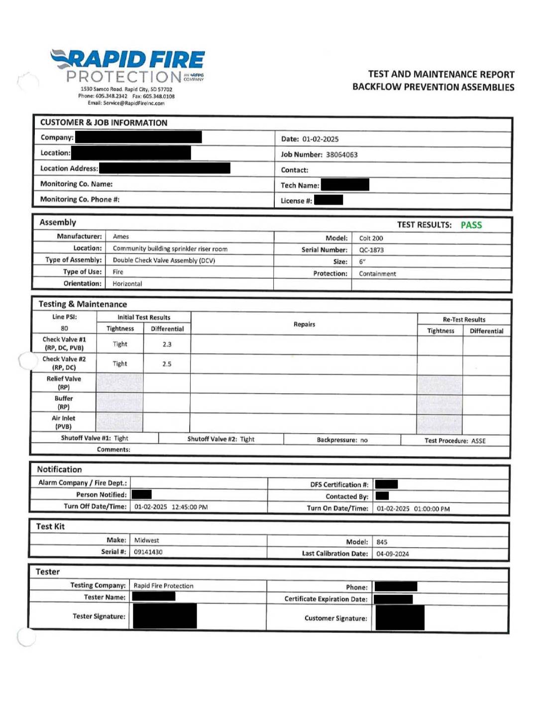
Image shows a completed “Test and Maintenance Report – Backflow Prevention Assemblies” from Rapid Fire Protection. The form documents the inspection of a double check valve assembly (DCVA) installed in a community building sprinkler riser room. The assembly passed all required tests, including tightness checks for both valves and differential prImage 1 Completed backflow prevention assembly test and maintenance report showing PASS results for a double check valve assembly.essure measurements. The report includes manufacturer and model information, test procedure (ASSE), line pressure, shutoff valve results, and confirmation that the assembly meets containment protection requirements. Notification fields, test kit details, and certification information are present, with identifying personal information redacted.
Example 2 shows a Quarterly Water‑Based Fire Protection Systems Inspection Report.
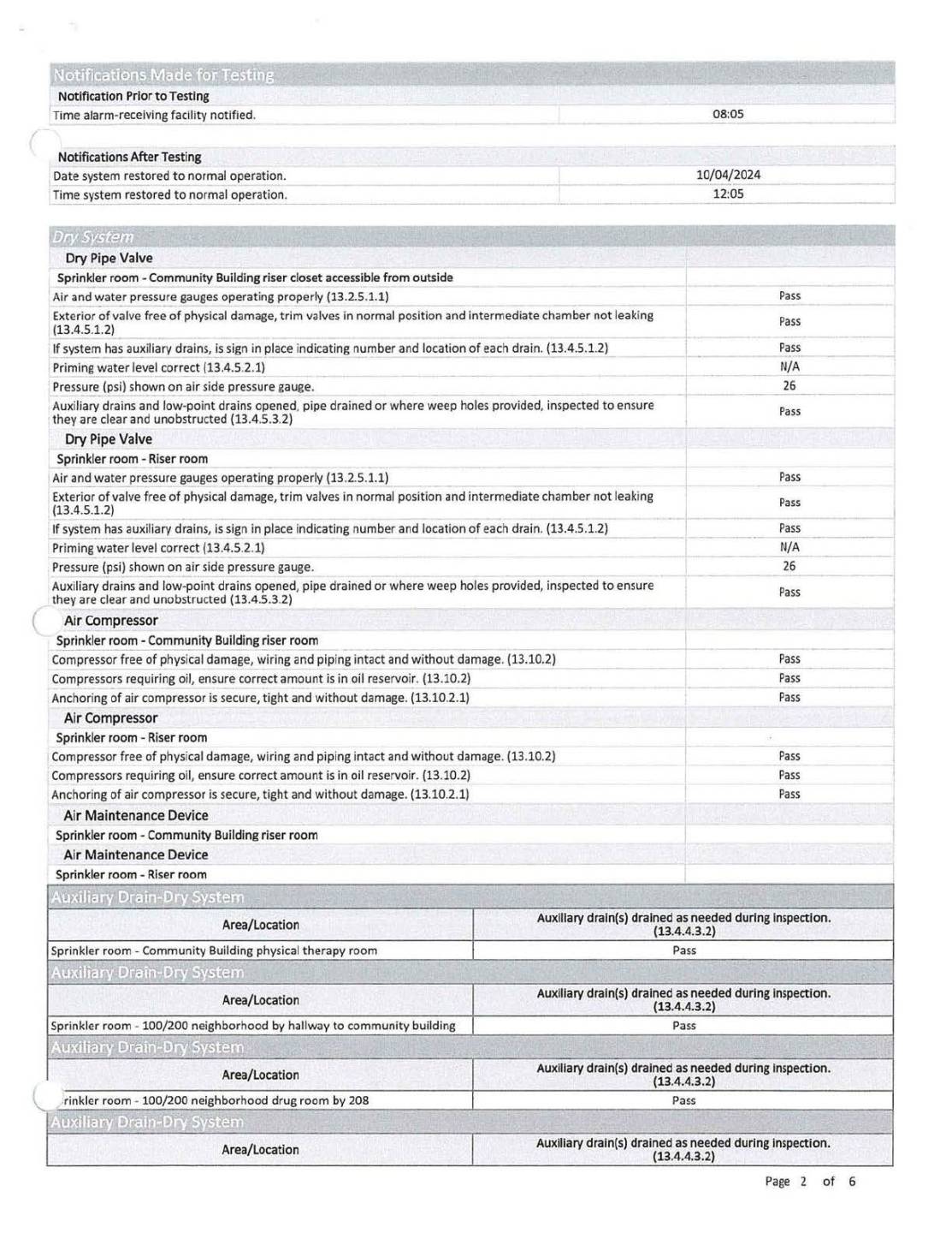
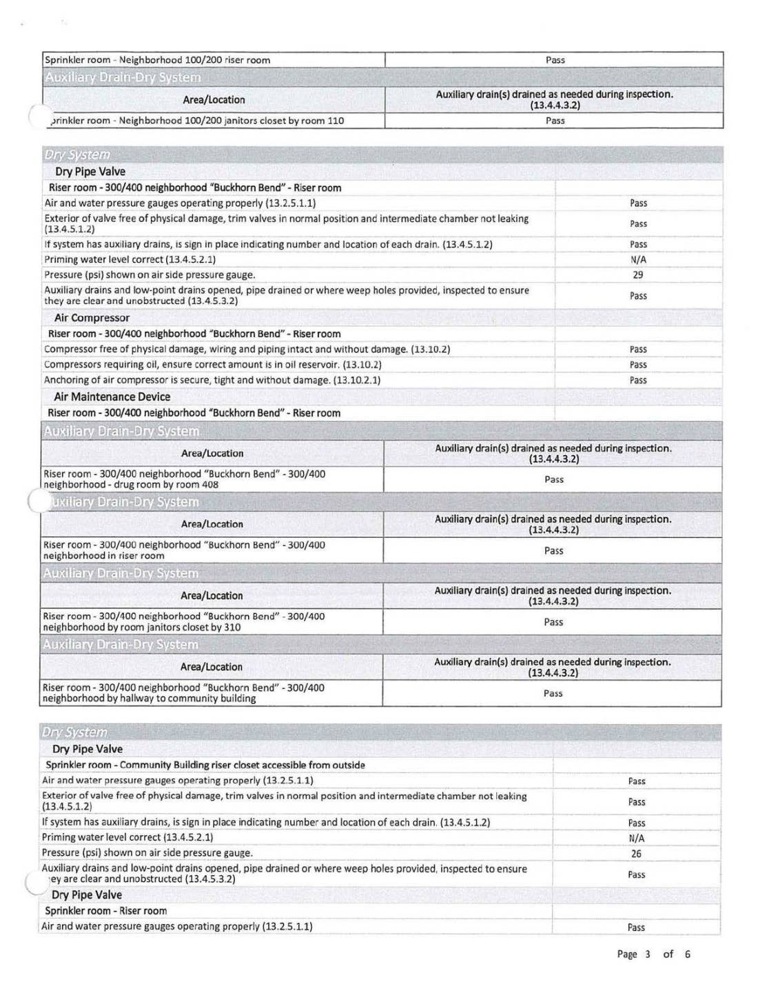
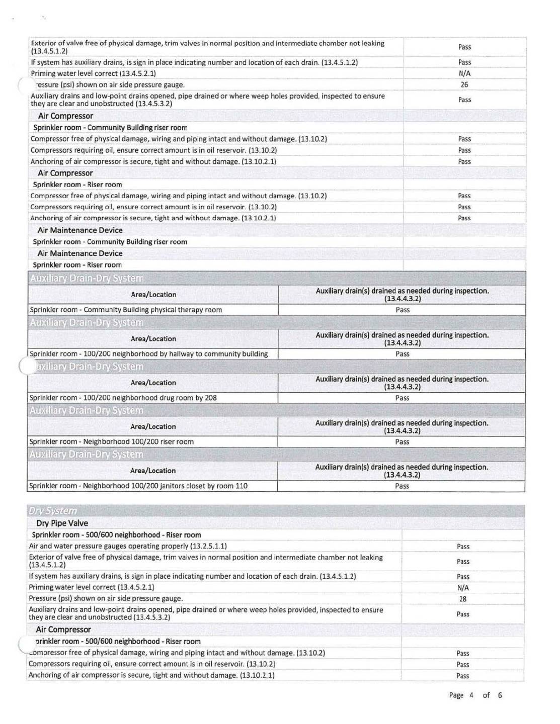
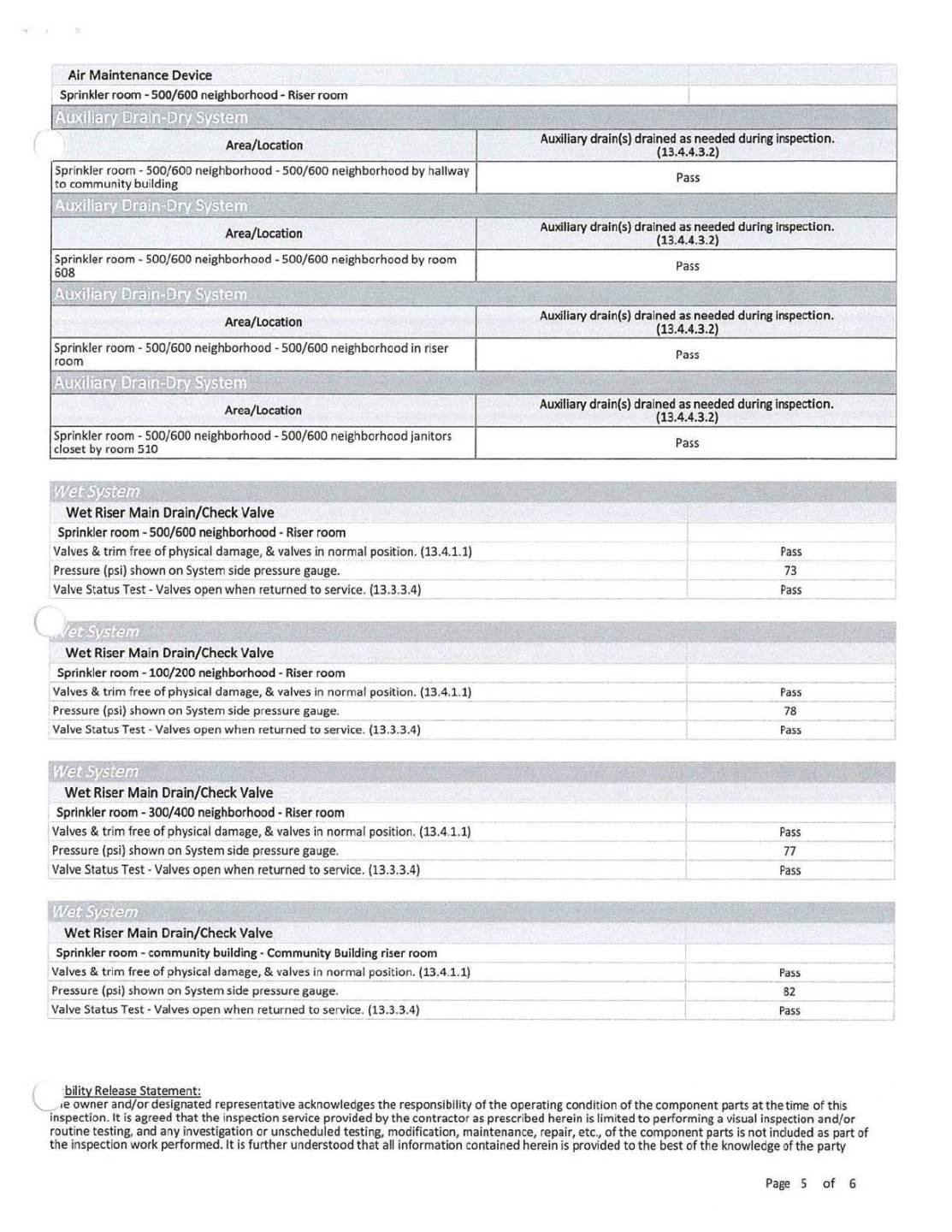
The images show a five‑page “Quarterly Water‑Based Fire Protection Systems Inspection” report completed according to NFPA 25. The report documents inspection results for dry pipe valves, wet riser systems, air compressors, air maintenance devices, and auxiliary drains across multiple sprinkler rooms and neighborhood riser rooms. Each section lists inspection criteria, NFPA code references, and pass/fail results, along with pressure readings and notes. Notification times, system restoration times, and liability statements are included. All identifying personal information has been redacted. The report indicates that all inspected components passed required quarterly inspection standards.
Example 3 shows a portable fire extinguisher inspection report.
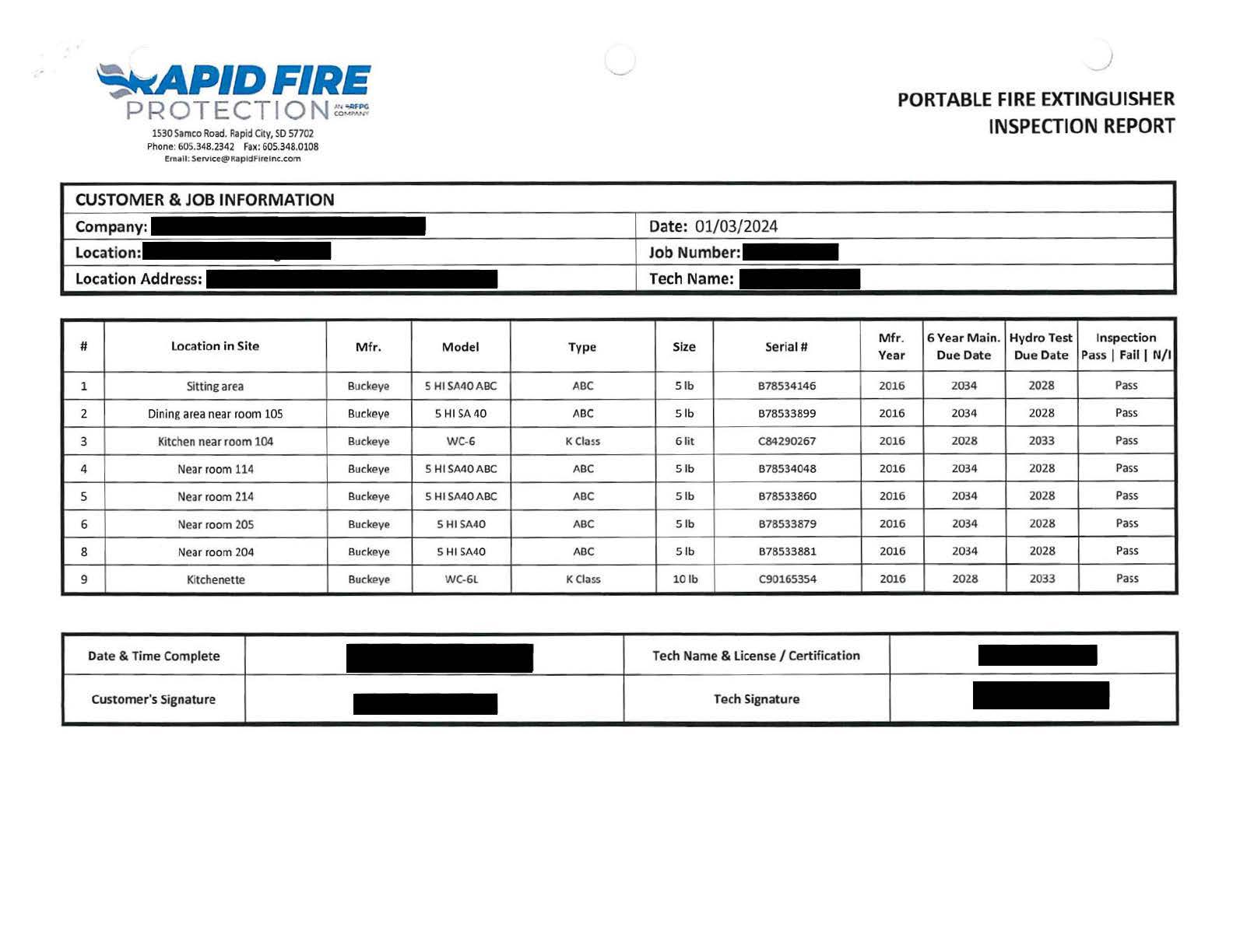
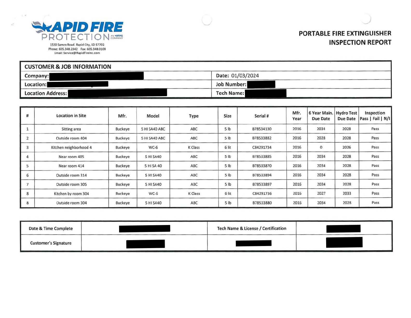
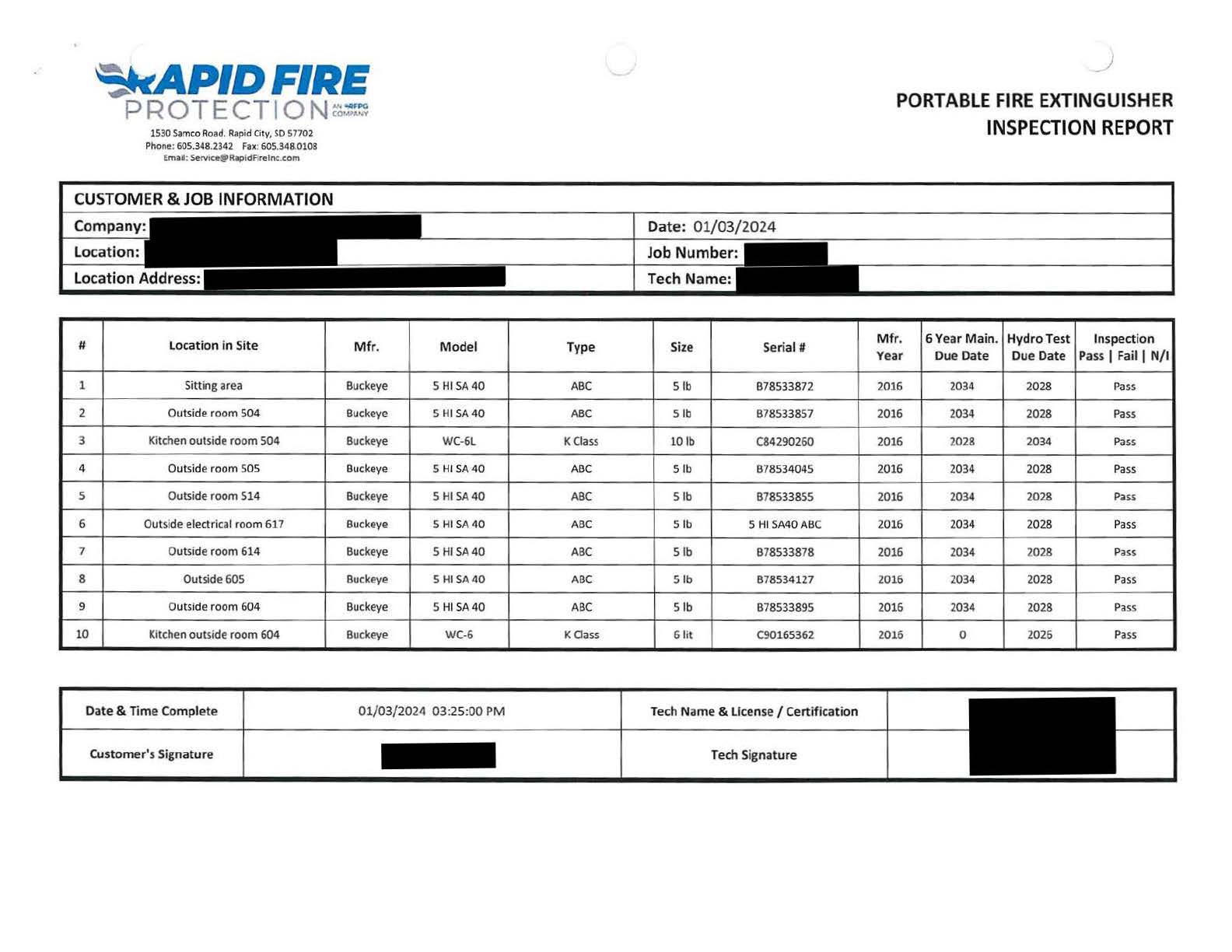
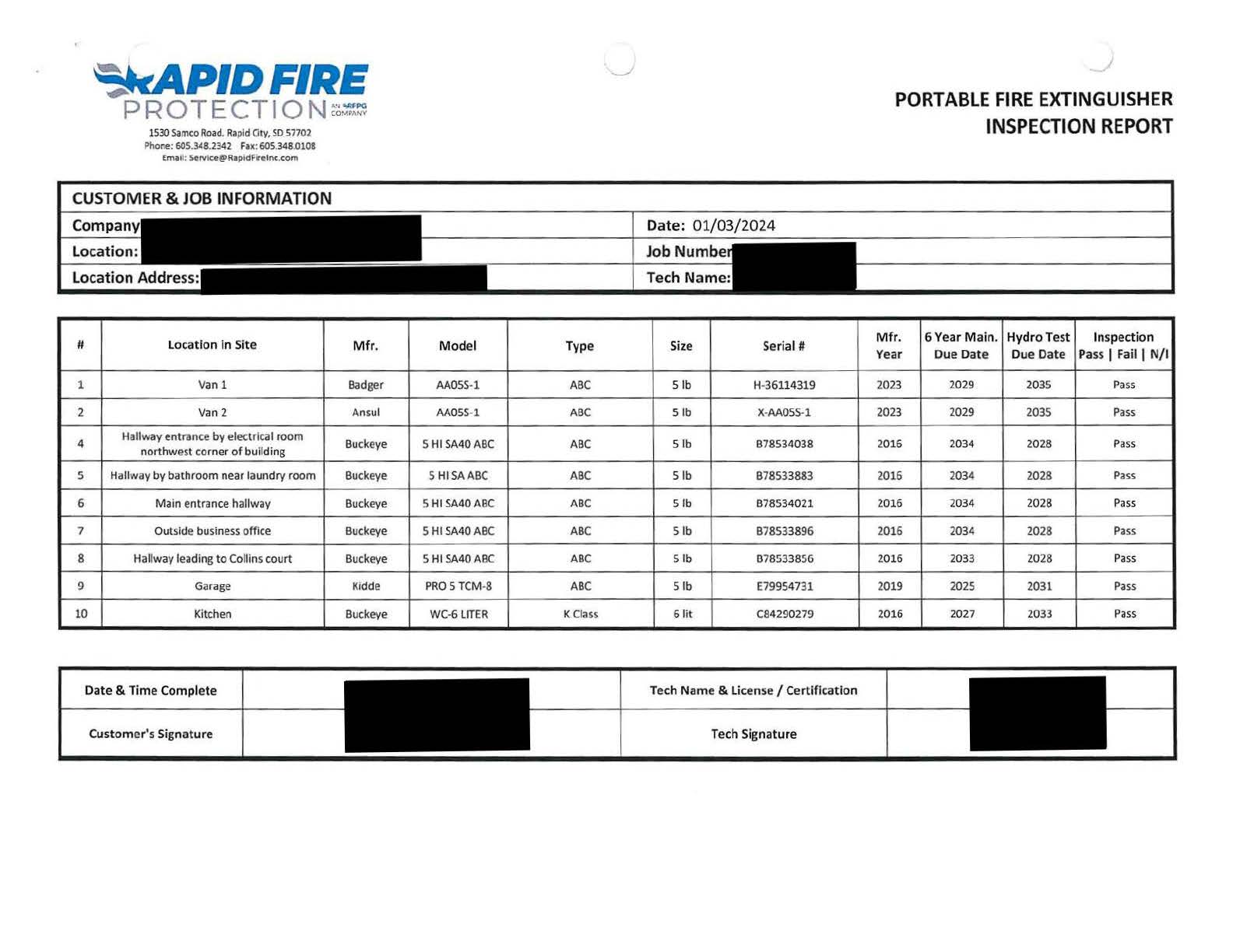
The images show a four-page Annual Portable Fire Extinguisher Inspection Report completed by Rapid Fire Protection. The report documents the yearly inspection results for fire extinguishers located throughout the facility, including sitting areas, hallways, kitchens, garages, and neighborhood wings. Each extinguisher entry lists manufacturer, model, type, size, serial number, manufacture year, six‑year maintenance due date, hydro test due date, and inspection status. All extinguishers in the report passed inspection. The document also includes job information, inspection date, technician fields, and customer signature fields, with identifying information redacted. The report verifies annual compliance with fire safety standards and confirms that all extinguishers are present, accessible, and within required maintenance intervals.
Battery Pack Emergency Lighting Records
Records shall be retained until the next test and for 1 year thereafter.
| Location | 30 Sec. | 90 Min. | Pass | Fail | Comments |
|---|---|---|---|---|---|
| Corridor by Room 108 | X | X | |||
| Corridor by Room 122 | X | X | |||
| Corridor by Room 208 | X | X | |||
| Corridor by Room 222 | X | ||||
| Corridor by Room 308 | X | X | |||
| Corridor by Room 322 | X | X | X | Replaced battery 01/21/2018 | |
| Corridor by Room 408 | X | X | |||
| Corridor by Room 422 | X | ||||
| Generator Room | X | X |
| Location | 30 Sec. | 90 Min. | Pass | Fail | Comments |
|---|---|---|---|---|---|
| Corridor by Room 108 | X | X | |||
| Corridor by Room 122 | X | X | |||
| Corridor by Room 208 | X | X | |||
| Corridor by Room 222 | X | ||||
| Corridor by Room 308 | X | X | |||
| Corridor by Room 322 | X | X | |||
| Corridor by Room 408 | X | X | |||
| Corridor by Room 422 | X | ||||
| Generator Room | X | X |
The image contains two tables titled “Battery Pack Emergency Light Tests January 2019” and “Battery Pack Emergency Light Tests February 2019.” Each table lists emergency light test results for multiple building locations, including corridors near rooms 108, 122, 208, 222, 308, 322, 408, 422, and the generator room. Columns include 30‑second test, 90‑minute test, pass, fail, and comments.
In the January table, all locations passed the 90‑minute test except the corridor by Room 322, which shows a fail and includes the comment “Replaced battery 01/21/2018.”
In the February table, all listed locations passed the 30‑second test and show pass results with no comments.
The tables document monthly emergency lighting functionality and compliance with required testing intervals.
Cubicle Curtains and Draperies Documentation
Documentation shall be retained for the duration of the item in the facility.

The image shows the header of the Cubicle Curtain Factory’s specifications for traditional cubicle curtains, which meet NFPA 701 standards. It includes the company’s contact information, the specification section title, and a small photo of a room with a cubicle curtain installed. This documentation is kept for the full duration of the curtain’s use in the facility.
Fire Alarm and Smoke Detectors Records
Fire Alarm system records shall be retained until the next test and for 1 year thereafter.
Smoke Detector sensitivity shall be checked within 1 year after installation. Sensitivity shall be checked every alternate year thereafter unless after the second required calibration test, if sensitivity tests indicate that the device has remained within its listed and marked sensitivity range, the length of time between calibration tests shall be permitted to be extended to a maximum of 5 years.
Semi-Annual Fire Alarm Battery Load Voltage Test
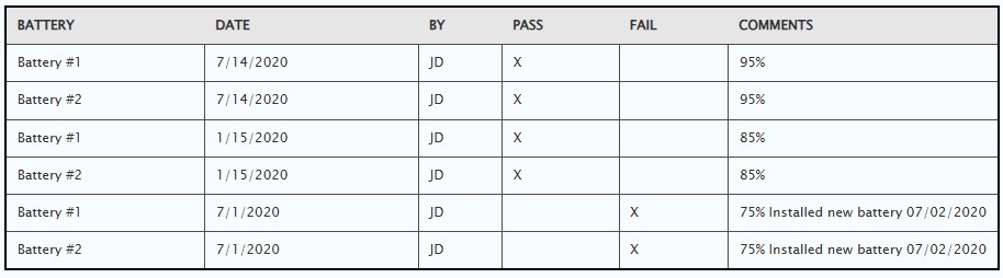
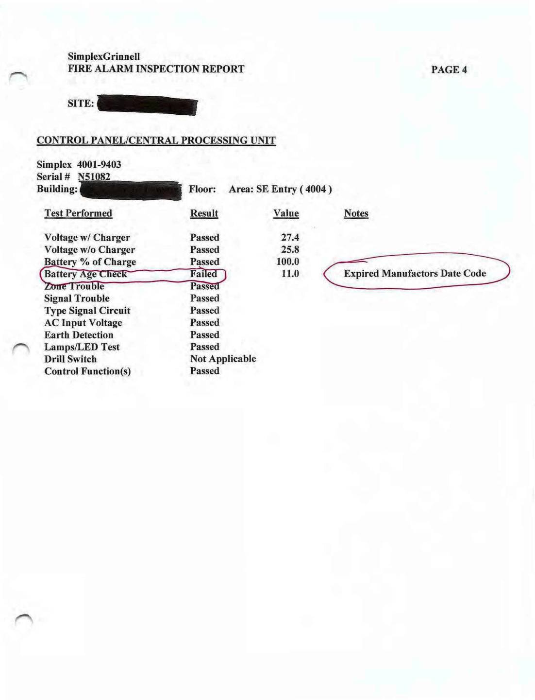
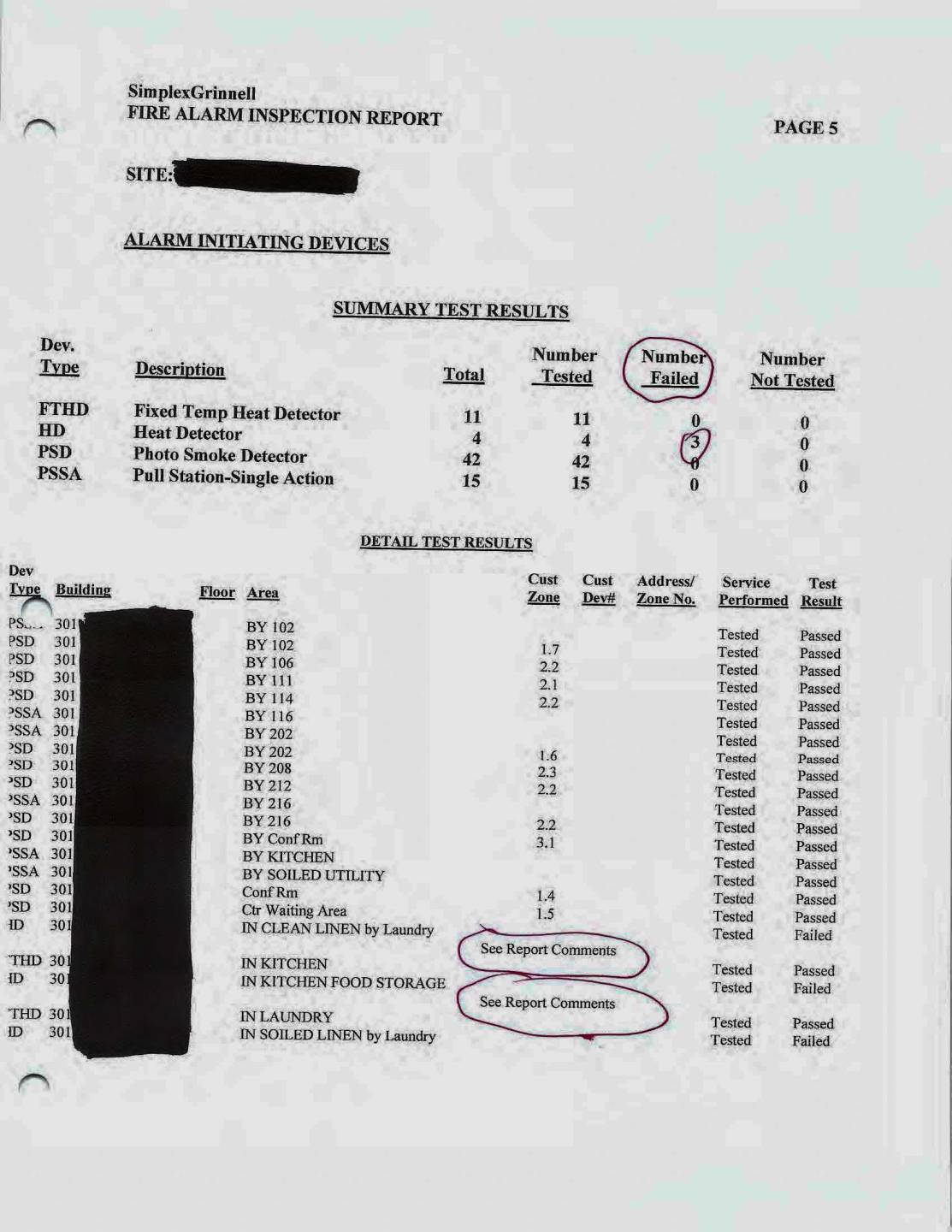
Example: Fire Alarm Inspection Report
Page 1:
SimplexGrinnell
FIRE ALARM INSPECTION REPORT
Performed in Accordance with Applicable National Fire Protection Association Standards
Inspection
PREPARED FOR
Facility
SimplexGrinnell
Page 2:
SimplexGrinnell
FIRE ALARM INSPECTION REPORT SITE: Facility
TABLE OF CONTENTS
Test Summary 1
Monitoring/Jurisdictional Agencies 2
Test Results - Control Panel/Central Processing Unit 3
Test Results - Alarm Initiating Devices 5
Test Results - Alarm Indicating Devices 8
Test Results - Control/Auxiliary Devices 11
Sensitivity Test Results 12
Inspection Deficiency Summary 14
Inspection Deficiencies 15
Image: Sample Fire Alarm Inspection Report
Fire Dampers Records
Each damper shall be tested and inspected 1 year after installation. The test and inspection frequency shall then be every 4 years, except in hospitals, where the frequency shall be every 6 years.
All documentation shall be maintained and made available for review by the AHJ.
Name of Facility:
Fire/Smoke Damper Test
| Department | damper code | Description/location - lower level | Date Test | test start time | Open Y/N | Closed Y/N | Pass Y/N | test stop time | Description of faults |
|---|---|---|---|---|---|---|---|---|---|
| surgery/PA | 12/31/2025 | 11:30 am | Y | Y | Y | 12:35 pm | |||
| Patient Acct | 12/31/2025 | 11:30 am | Y | Y | Y | 12:35 pm | |||
| Patient Acct | 12/31/2025 | 11:30 am | Y | Y | Y | 12:35 pm | |||
| Patient Acct | 12/31/2025 | 11:30 am | Y | Y | Y | 12:35 pm | |||
| Patient Acct | 12/31/2025 | 11:30 am | Y | Y | Y | 12:35 pm | |||
| Patient Acct | 12/31/2025 | 11:30 am | Y | Y | Y | 12:35 pm | |||
| IT Closet | 12/31/2025 | 11:30 am | Y | Y | Y | 12:35 pm | |||
| ClinicwaitRm | 12/31/2025 | 11:30 am | Y | Y | Y | 12:35 pm | |||
| ClinicwaitRm | 12/31/2025 | 11:30 am | Y | Y | Y | 12:35 pm | |||
| Eve Clinic | 12/31/2025 | 11:30 am | Y | Y | Y | 12:35 pm | |||
| IT Storage | 12/31/2025 | 11:30 am | Y | Y | Y | 12:35 pm | |||
| IT Storage | 12/31/2025 | 11:30 am | Y | Y | Y | 12:35 pm | |||
| Clinic hall | 12/31/2025 | 11:30 am | Y | Y | Y | 12:35 pm | |||
| Clinic PR-A | 12/31/2025 | 11:30 am | Y | Y | Y | 12:35 pm | |||
| Clinic PR-A | 12/31/2025 | 11:30 am | Y | Y | Y | 12:35 pm | |||
| AHU-4 | 12/31/2025 | 11:30 am | Y | Y | Y | 12:35 pm | |||
| Clinic | 12/31/2025 | 11:30 am | Y | Y | Y | 12:35 pm | |||
| Clinic | 12/31/2025 | 11:30 am | Y | Y | Y | 12:35 pm | |||
| Clinic | 12/31/2025 | 11:30 am | Y | Y | Y | 12:35 pm | |||
| Clinic | 12/31/2025 | 11:30 am | Y | Y | Y | 12:35 pm | |||
| Clinic | 12/31/2025 | 11:30 am | Y | Y | Y | 12:35 pm | |||
| Clinic | 12/31/2025 | 11:30 am | Y | Y | Y | 12:35 pm | |||
| Ultrasound Hall | S door N 6x85 to be installed | ||||||||
| Ultrasound Hall | S door S 6x85 to be installed | ||||||||
| Medsurg | S door S 12x85 to be installed | ||||||||
| Medsurg | E door ctr 4x85 to be installed |
Fire Door Inspection Records
Periodic inspections and testing shall be performed not less than annually. Records shall be retained for a period of at least 3 years.
What to look for during a door inspection
- Is the door and frame free from holes and breaks in all surfaces?
- Are all the glazing, vision light frames and glazing beads intact and securely fastened?
- Are the doors, hinges, frame, hardware and threshold secure, aligned and in working order with no visible signs of damage?
- Is the door free from missing or broken parts?
- Is the clearance from the door edge to the frame no more than 1/8 inch?
- Is the door undercut no more than¾ inch?
- Does the active door leaf completely close when operated from the full open position?
- Does the inactive·leaf close before the active leaf when a coordinator is used?
- Does the latching hardware operate and secure the door in the closed position?
- Is the door assembly free from any auxiliary hardware items which could interfere with its operation?
- Is the door free from any modifications since it was originally installed?
- If gasketing and edge seals are installed, have they been verified for integrity and operation?
- Is 95% of the surface of the door free from signage?
Fire Door Locations
Floor plan labeled ‘Fire Door Locations’ with nine red numbered circles marking fire door positions throughout the building.
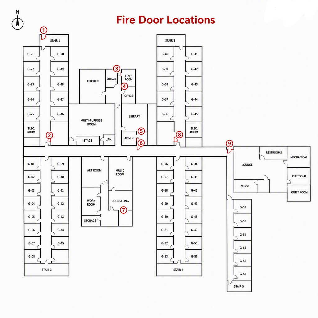
The image shows a building floor plan titled “Fire Door Locations.” Nine red circled numbers identify fire door positions at key corridor intersections and entry points. The layout includes multiple rooms and hallways, illustrating where fire‑rated doors are installed for safety and compliance.
Annual Fire Door Inspection
| Date | Fire Door | Pass | Fail | Comments |
|---|---|---|---|---|
| 6/24/2025 | 1 | X | ||
| 6/24/2025 | 2 | X | ||
| 6/24/2025 | 3 | X | ||
| 6/24/2025 | 4 | X | ||
| 6/24/2025 | 5 | X | Failed to latch – Repair made 6/25/2025 | |
| 6/24/2025 | 6 | X | ||
| 6/24/2025 | 7 | X | ||
| 6/24/2025 | 8 | X | ||
| 6/24/2025 | 9 | X |
Fire Drill Records - 1 per shift per quarter
Records shall be retained until the next drill and for 1 year thereafter.
| Month / Day / Year | AM Shift 6:00 am – 2:00 pm | PM Shift 2:00 pm – 10:00 pm | Night Shift 10:00 pm – 6:00 am |
|---|---|---|---|
| January 23, 2026 | 6:28 AM | ||
| February 15, 2026 | 3:14 PM | ||
| March 20, 2026 | 2:15 AM | ||
| April | |||
| May | |||
| June | |||
| July | |||
| August | |||
| September | |||
| October | |||
| November | |||
| December |
| Month / Day / Year | AM Shift 6:00 am – 2:00 pm | PM Shift 2:00 pm – 10:00 pm | Night Shift 10:00 pm – 6:00 am | Full Evacuation 1 Per Year |
|---|---|---|---|---|
| January | ||||
| February | ||||
| March | ||||
| April | ||||
| May | ||||
| June | ||||
| July | ||||
| August | ||||
| September | ||||
| October | ||||
| November | ||||
| December |
Sample Fire Drill Report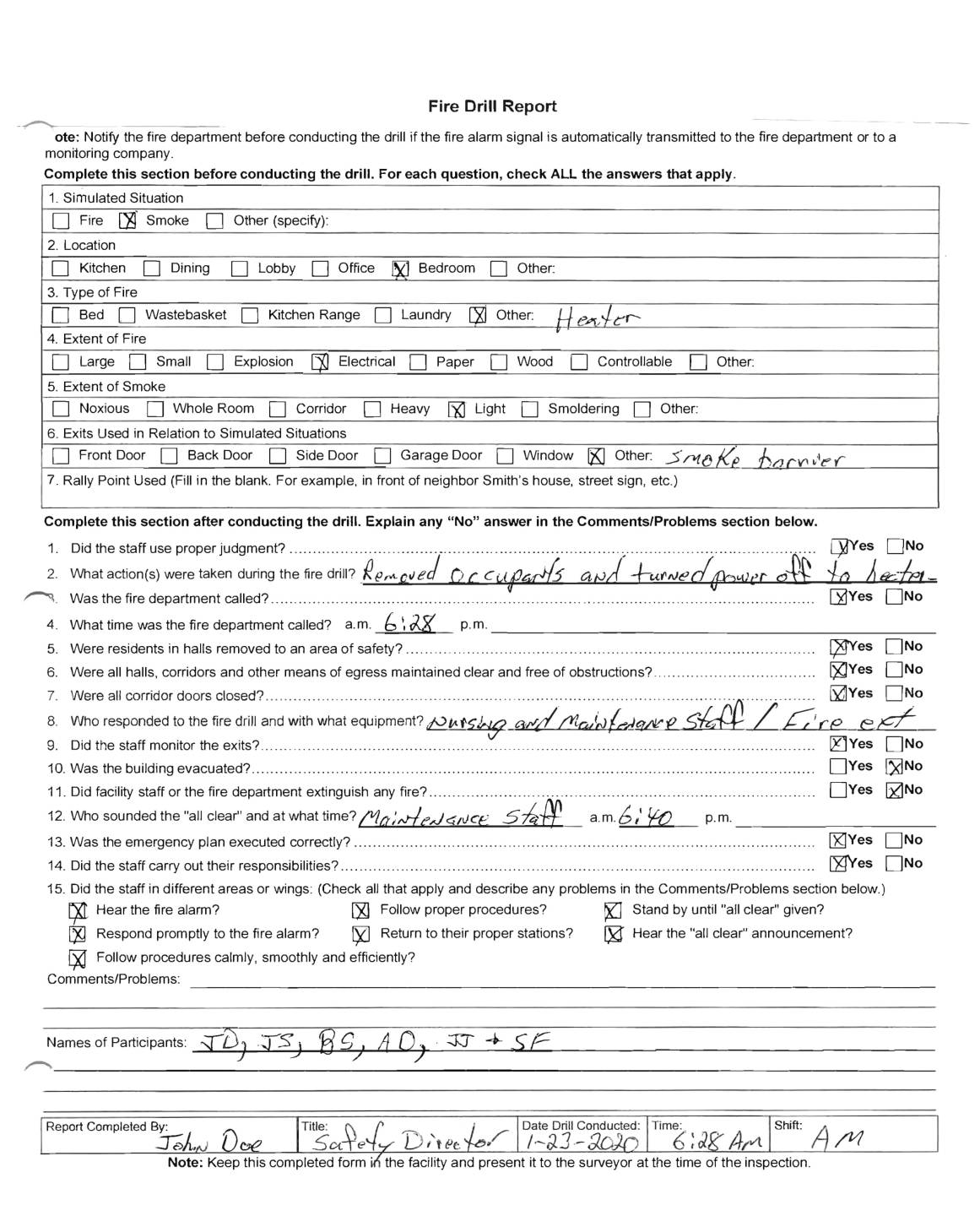
The image shows a completed Fire Drill Report form used to document a simulated fire drill. The form includes checked boxes indicating the simulated situation was a fire in an office and bedroom, caused by a heater. The fire was small with light smoke, and the smoke barrier was used as the exit. Staff removed occupants, turned off power to the heater, and did not call the fire department. The report confirms that corridors were clear, doors were closed, exits were monitored, and the emergency plan was executed correctly. Nursing and maintenance staff responded with a fire extinguisher, and the “all clear” was given at 6:40 p.m.
Floor Finish Documentation - New only
Documentation shall be retained for the duration of the product in the facility.
Image: Example of flooring product and safety specifications Page 1 of 2.
Image shows the following specifications:
ASTM E648 - Critical Radiant Flux (Radiant Panel): Passes Requirements for Class I per International Building Code (IBC) 2018 & NFPA 101 Life Safety Code.
2 ASTM E662 - Smoke Density: 450 is the limit established by many state, county, and/or local building and/or fire codes, but is not set as a limit for (resilient) flooring products
nationwide. Thus, Smoke Density requirements for flooring products may vary from jurisdiction to jurisdiction. Consult your building inspector / fire marshal to learn more.
3 CPSIA = Consumer Product Safety Improvement Act.
4 Product tested uninstalled.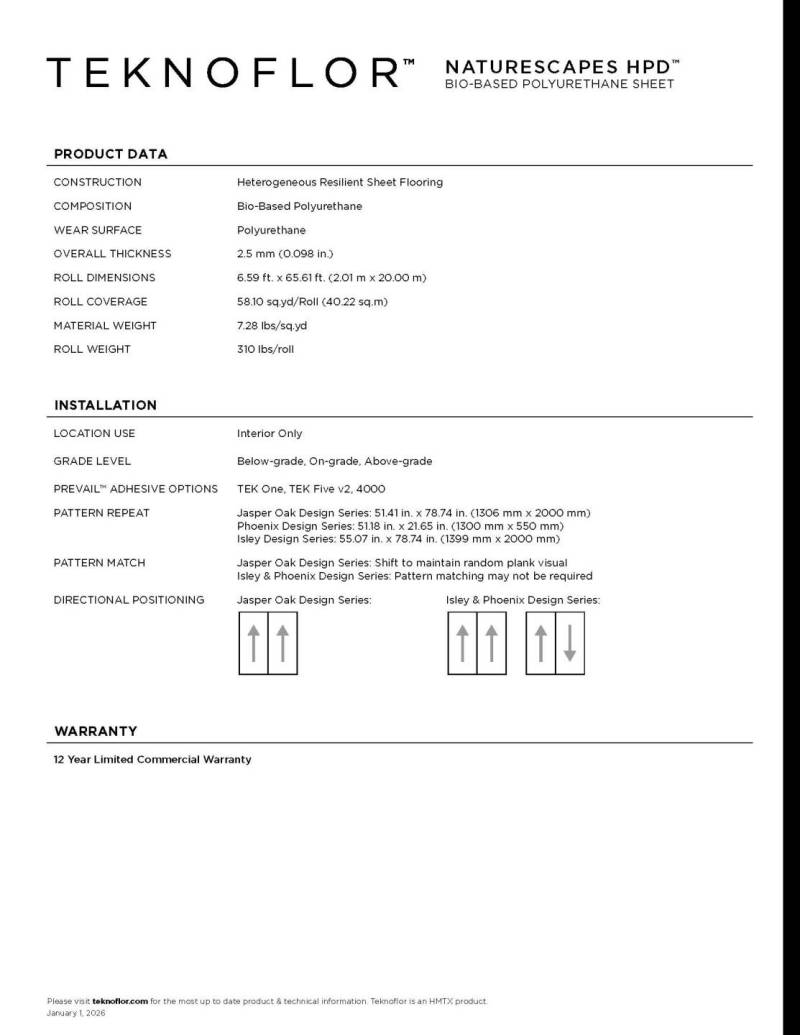
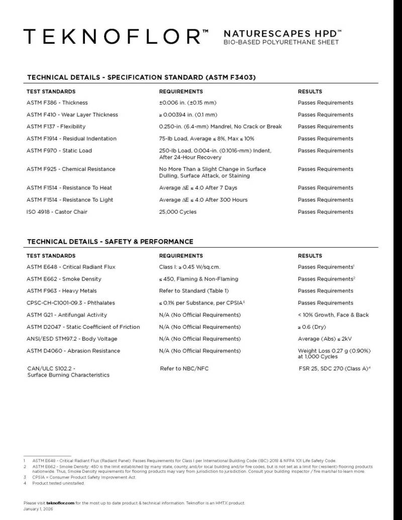
The document is a TEK Naturescapes product specification sheet. It includes manufacturer information, product features, technical performance data, installation guidelines, and compliance statements. The sheet outlines material composition, durability ratings, maintenance instructions, and any applicable safety or environmental certifications. This specification is retained for the duration of the product’s use in the facility.
Furnishings and Mattresses Documentation
Documentation shall be retained for the duration of the item in the facility.
Example of documentation:
Direct Supply
Simple Sleep
Foam Mattress
Owner's Manual
Thank you for purchasing a Simple Sleep Foam Mattress. Please read this entire manual carefully and keep it for future reference. This manual will provide you with instructions, warnings, warranty information and other important information about your mattress. Share this information with individuals who will be assembling, using, servicing and/or cleaning the product to help ensure it is cared for properly.
Product Specifications
Cover:
Two-way stretch top cover with backing
Heavy-duty, nonskid bottom cover
Antimicrobial, breathable, fluid-resistant, low-shear. tear-resistant, ¾ concealed zipper
Fire Ratings:
16 CFR 1633, 16 CFR 1632
Weight Capacity
Weight Capacity Weight
Product Part (lbs.) Capacity (kg)
Direct Supply Simple Sleep Foam Mattress 300 lbs 36kg
Directions for Use
- To ensure full mattress expansion, the mattress must be unpackaged within 48 hours of receipt. Do not use razor blades to cut packaging away from mattress.
- Unpack the mattress in an area with sufficient room to work. Do not allow children, animals or individuals with impaired cognitive or physical abilities near the product until it has been completely set up and the work area has been cleared of all debris.
- Inspect the mattress for shipping damage. If the mattress is damaged, DO NOT USE MATTRESS and immediately contact the distributor for further instruction.
- Verify the proper mattress model and size was shipped. If you feel there was a mistake. DO NOT USE MATTRESS and immediately contact the distributor.
- After verifying you've received the correct product without damage, properly discard all shipping materials.
- Place the mattress on the bed frame and secure as necessary.
- Compressed mattresses need time to properly recover. Allow the mattress to recover for 24 hours before using.
- After 24 hours, the mattress is ready to use. If after 24 hours the mattress does not appear to have properly recovered. DO NOT USE MATTRESS and immediately contact the distributor.
NOTE: Do not remove product tag, cleaning instruction tag or law tag from the mattress. Removal of tags will void the warranty.
NOTE: Always make sure the "Foot End" label of the mattress is positioned at the foot end of the bed.
Generator and Transfer Switch Records
A permanent record of the EPSS inspections, tests, exercising, operation, and repairs shall be maintained and readily available.
Example of Emergency Generator Weekly Inspection Checklist.
| Inspection Item | 9/18/08 | 9/25/08 | 10/2/08 | Comments / Corrective Actions |
|---|---|---|---|---|
| Date of inspection | 9/18/08 | 9/25/08 | 10/2/08 | |
| Inspection performed by | JJS | JJS | JJS | |
| General condition of prime mover/generator | OK | OK | OK | |
| Condition of belts & hoses | OK | OK | OK | |
| Engine oil level | OK | OK | OK | Checked with engine stopped |
| Lube oil heater | OK | OK | OK | |
| Coolant level | OK | OK | OK | |
| Water pump | OK | OK | OK | |
| Jacket water heater | OK | OK | OK | |
| Radiator | OK | OK | OK | (10/2/08) Cores need cleaning – Done |
| Electrical/Generator breaker closed | OK | OK | OK | |
| Battery system | OK* | OK | OK | (9/18/08) Topped off electrolyte |
| Electrolyte level | OK | OK | OK | Normal = 1250 |
| Charger | OK | OK | OK | Reads less than 1 amp |
| Exhaust system | OK | OK | OK | |
| Fuel system | OK | OK | OK | |
| Fuel supply level | OK* | OK | OK | (9/25/08) ½ full, fuel added |
| Tank vent(s) | OK | OK | OK |
Example: Emergency Generator Monthly Test Log
| Month | Test Date | Time Meter Reading Start | Time Meter Reading End | Transfer Switch Inspection | Transfer Switch Test | Battery Specific Gravity | Oil Pressure | Operating Temp | Load kW | Tested By | Comments |
|---|---|---|---|---|---|---|---|---|---|---|---|
| January | 1/3/09 | 147 | 147.8 | OK | OK* | 1255 | 47 psi | 191° | 231 | JD | *8 seconds to load transfer |
| February | 2/1/09 | 153.1 | 153.8 | OK | OK* | 1250 | 49 psi | 193° | 234 | JD | *7 seconds to load transfer |
| March | 3/2/09 | 162.2 | 163 | OK | OK* | 1260 | 46 psi | 190° | 234 | JD | *8 seconds to load transfer |
| April | |||||||||||
| May | |||||||||||
| June | |||||||||||
| July | |||||||||||
| August | |||||||||||
| September | |||||||||||
| October | |||||||||||
| November | |||||||||||
| December | Sales and Service Example of Planned Maintenance Checklist | ||||||||||
Image: Example of a Planned Maintenance Checklist Page 1.
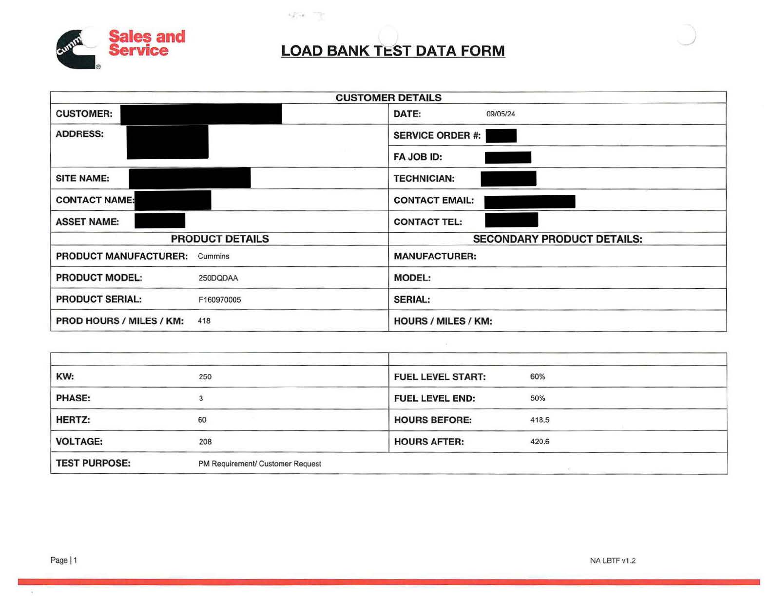
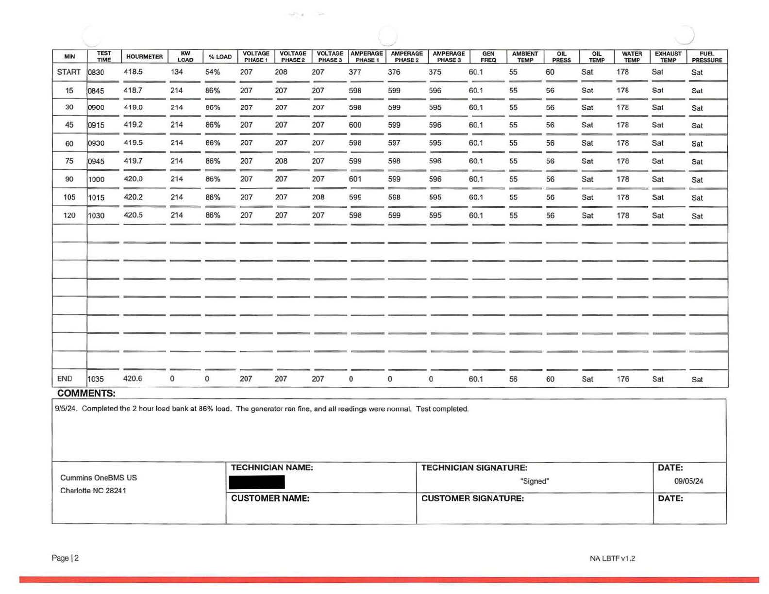
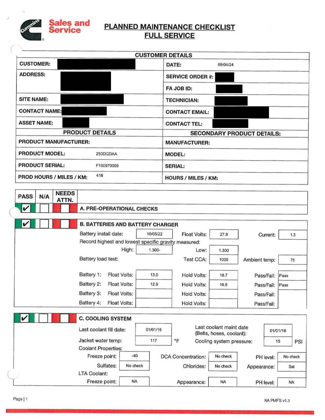
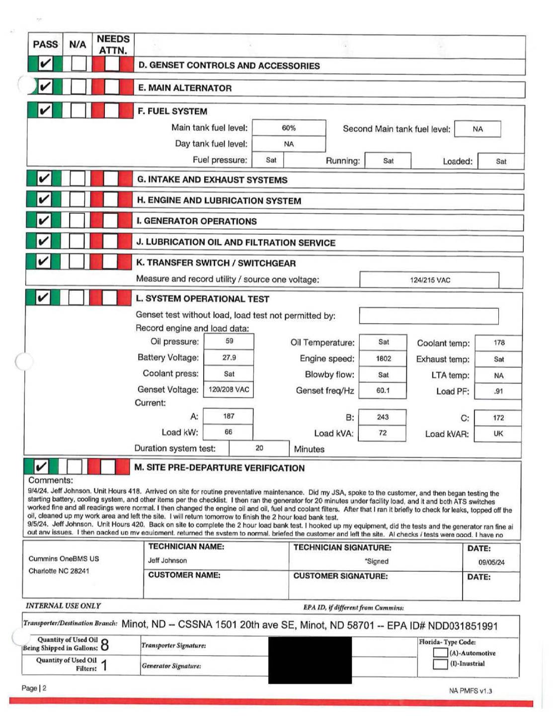
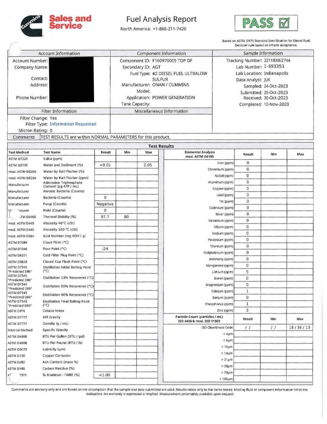
The five-page document includes three related service reports for a generator. The first report is a Load Bank Test Data Form that lists customer details, site information, generator manufacturer, model, serial number, and operating hours. It also contains electrical specifications for the test, such as kilowatts, voltage, phase, hertz, and fuel levels before and after testing. Several identifying fields throughout the form are redacted.
The second report provides a detailed test log recorded at multiple time intervals during the load bank test. Each row includes readings for load percentage, voltage across phases, amperage, generator frequency, oil temperature, water temperature, exhaust temperature, and fuel pressure. A comment at the bottom states the generator ran normally and the test was completed. Technician and customer signature sections appear at the bottom, with personal information obscured.
The third report is a Planned Maintenance Checklist for full-service maintenance. It shows customer information and equipment details similar to the first report, with portions blacked out. The checklist includes completed sections for pre-operational checks, batteries and battery charger, and cooling system. Measurements such as battery voltages, coolant temperature, test values, and maintenance dates are recorded. Each section shows pass indicators for the work completed.
Diesel Generator Load Calculation (NFPA 110)
Amps: L1 ___ + L2 ___ + L3 ___ = Amps / 3 = ___ Avg Amps
Avg Amps:___x Volts:____x 1.732 (for 3ph) / 1000 = ____ Load KW
Load KW:____ / Name Plate KW:____=____% of Name Plate KW
If final KW calculation is greater than 30% of name plate value = "Pass"
If final KW calculation is less than 30% of name plate value = "Fail"
Example of Diesel Generator Load Calculation:
Amps: L1 50 + L2 49 + L3 51 = Amps / 3 = 50 Avg Amps
Avg Amps: 50 x Volts 480 x 1.732 (for 3ph) / 1000 = 41 Load KW
Load KW: 41 / Name Plate KW: 250 = 16 % of Name Plate KW
If final KW calculation is greater than 30% of name plate value = "Pass"
If final KW calculation is less than 30% of name plate value = "Fail"
Note: 1 Kiloampere = 1000 Amps
Interior Finish Documentation:
- Inspection:
- Hoods shall be inspected monthly with date noted on log sheet.
- Semiannually – maintenance and inspection for cleaning shall be conducted.
- Records:
- Documentation shall be retained for the duration of the product in the facility.
- Product Information Sheet:
- Floors
- Description
- Product Specifications
- Physical Properties
- Fire Hazard Classification:
- Fire Rating: ASTM E-84 or ANSI/UL 723
- Flame Spread: 25
- Smoke Developed: 20
- Fire Rating: ASTM E-84 or ANSI/UL 723
- Walls
- Description
- Product Specifications
- Physical Properties
- Fire Hazard Classification:
- Fire Rating: See Chapter 10, Table 10.2 of NFPA 101 for the appropriate test method which will define the Flame Spread and Smoke Developed standards.
Documentation shall be retained for the duration of the product in the facility
Image: Example Commercial Wallpaper Specifications
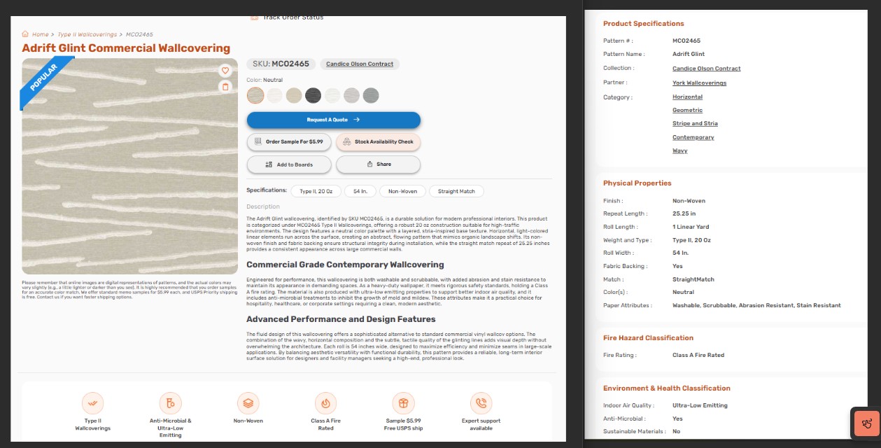
This image provides product information for the Adrift Glint 37087 commercial wallcovering. It includes the pattern name, color details, application type, and availability status, along with manufacturer and collection information. The page outlines technical specifications such as material type, physical properties, and performance characteristics. Additional sections offer related products, customer service contact options, and links to company resources. This product information is retained as part of facility documentation for interior finishes and compliance reference.
Portable Fire Extinguishers Records
Where monthly manual inspections are conducted, records for manual inspections shall be kept on a tag or label attached to the fire extinguisher, on an inspection checklist.
Fire extinguishers inspected via electronic monitoring, whereby the extinguisher causes a signal at a control unit when a deficiency occurs, shall provide record keeping in the form of an electronic event log at the control panel. Where electronically monitored systems are employed for inspections, records shall be kept for fire extinguishers found to require corrective action.
Records shall be kept demonstrating that at least the last 12 monthly inspections have been performed.
Image: Example of a Facility floor plan with Fire Extinguisher locations.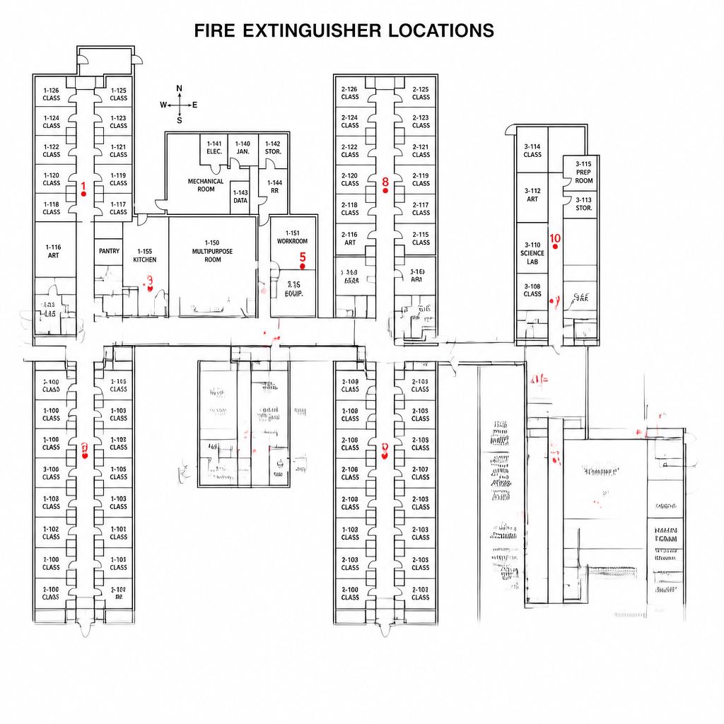
The image shows a detailed building floor plan titled “Fire Extinguisher Locations.” Ten fire extinguisher positions are marked with red numbered circles placed throughout the facility. The layout includes classrooms, art rooms, a science lab, kitchen, multipurpose room, mechanical and electrical rooms, storage areas, and connecting corridors. A compass rose indicating north, south, east, and west appears near the top of the diagram. The diagram provides a clear visual reference for where fire extinguishers are located within the building to support emergency preparedness and Life Safety compliance.
Example: Monthly Fire Extinguisher Inspection Log
Monthly Fire Extinguisher Inspections
January 2026
| Extinguisher | Date | By | Pass | Fail | Comments |
|---|---|---|---|---|---|
| Extinguisher 1 | 1/15/26 | JD | X | ||
| Extinguisher 2 | 1/15/26 | JD | X | ||
| Extinguisher 3 | 1/15/26 | JD | X | ||
| Extinguisher 4 | 1/15/26 | JD | X | ||
| Extinguisher 5 | 1/15/26 | JD | X | ||
| Extinguisher 6 | 1/15/26 | JD | X | ||
| Extinguisher 7 | 1/15/26 | JD | X | ||
| Extinguisher 8 | 1/15/26 | JD | X | ||
| Extinguisher 9 | 1/15/26 | JD | X | ||
| Extinguisher 10 | 1/15/26 | JD | X | ||
| Extinguisher 11 | 1/15/26 | JD | X | ||
| Extinguisher 12 | 1/15/26 | JD | X | ||
| Extinguisher 13 | 1/15/26 | JD | X | ||
| Extinguisher 14 | 1/15/26 | JD | X | ||
| Extinguisher 15 | 1/15/26 | JD | X | ||
| Extinguisher 16 | 1/15/26 | JD | X |
Example of Annual Inspection Report
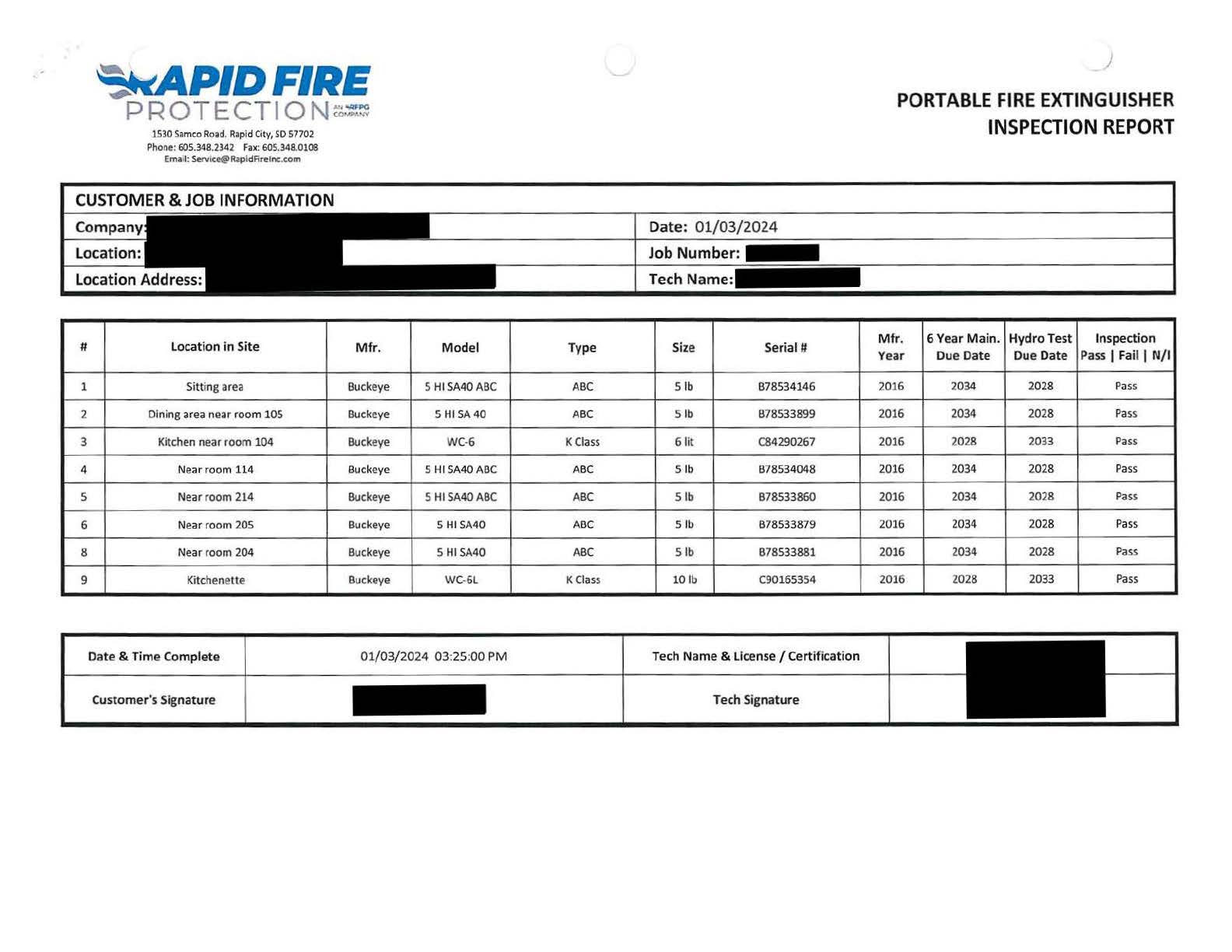
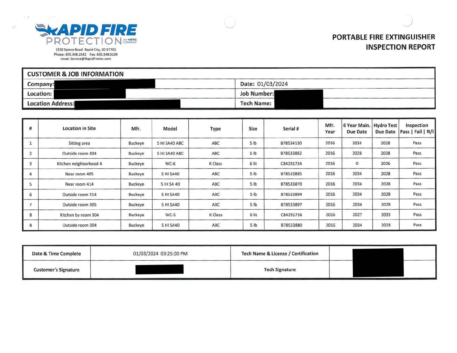
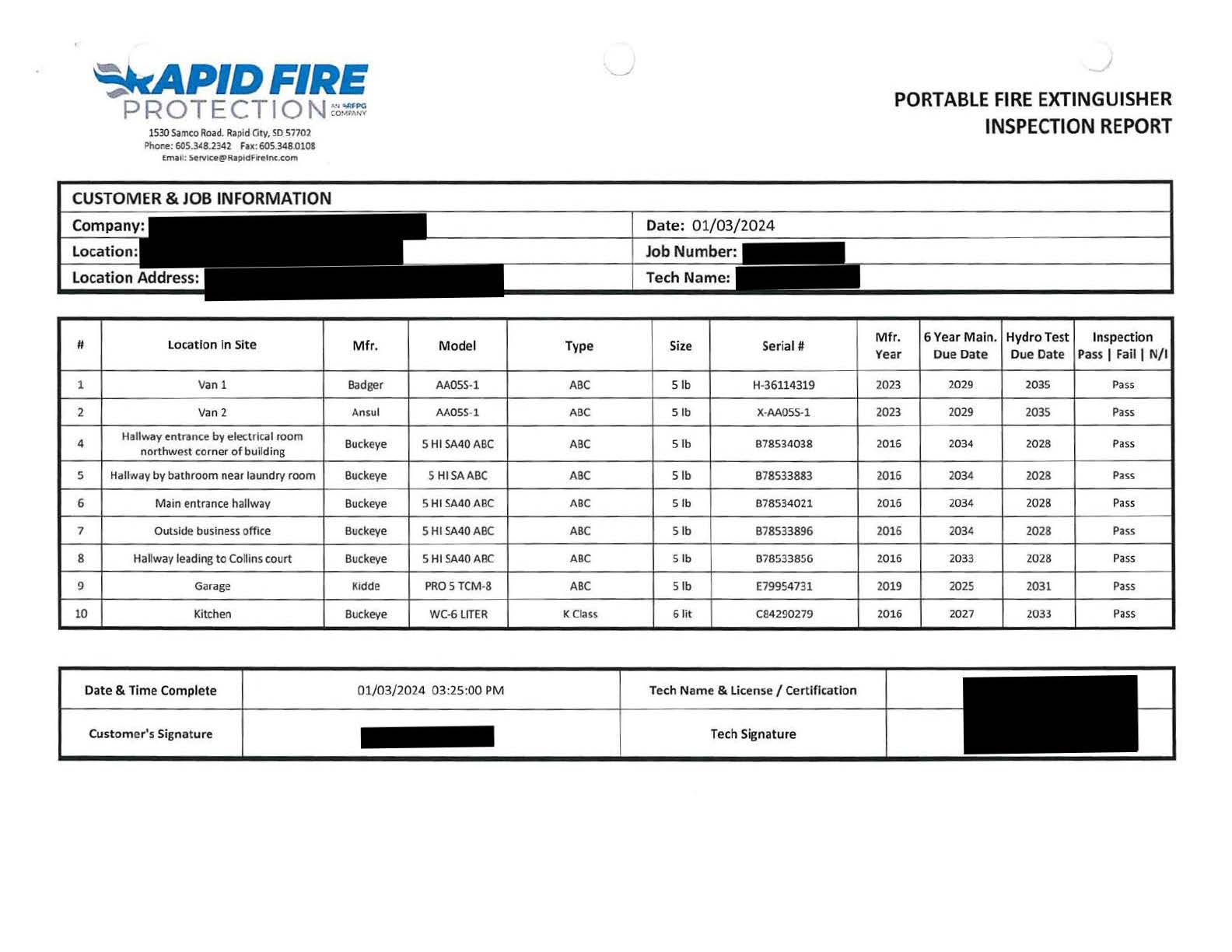
The image is a scanned four‑page Portable Fire Extinguisher Inspection Report from Rapid Fire Protection. The top-left corner shows the company logo and contact information for a Rapid City, South Dakota office. At the top-right, the title reads “Portable Fire Extinguisher Inspection Report.”
Below the header is a section labeled “Customer & Job Information.” It includes labeled fields for Company, Location, Location Address, Date (01/03/2024), Job Number, and Tech Name. Several fields have blacked‑out text indicating redacted information.
The main portion of the document is a table with nine rows, each representing an extinguisher inspected. Columns include:
- “#” (extinguisher number),
- “Location in Site,”
- “Mfr.” (manufacturer),
- “Model,”
- “Type,”
- “Size,”
- “Serial #,”
- “Mfr. Year,”
- “6 Year Main. Due Date,”
- “Hydro Test Due Date,”
- “Inspection Pass | Fail | N/I.”
Locations listed include sitting area, dining area near room 105, kitchen near room 104, near room 114, near room 214, near room 205, near room 204, and a kitchenette. Most extinguishers are labeled “Buckeye” with ABC type and 5‑pound size, with two K‑Class units in the kitchen and kitchenette. All inspection results in the final column read “Pass.”
At the bottom of the page is a section titled “Date & Time Complete,” showing 01/03/2024 at 03:25 PM. Spaces for Customer’s Signature and Tech Name & License/Certification contain blacked‑out entries. A final boxed field labeled “Tech Signature” also contains redacted text.
Range Hood System Records
At least monthly, the date the inspection is performed and the initials of the person performing the inspection shall be recorded. Records shall be retained for the period between the semiannual maintenance inspections.
At least semiannually, maintenance and inspection for cleaning shall be conducted. Records shall be retained for a period of 1 year after the next required maintenance and inspection for cleaning.
Example: Monthly Range Hood Extinguishing System Inspections
| Month | Day | By | Pass | Fail | Comments |
|---|---|---|---|---|---|
| January | 1/15/26 | JD | |||
| February | 1/15/26 | JD | |||
| March | 1/15/26 | JD | |||
| April | 1/15/26 | JD | |||
| May | 1/15/26 | JD | |||
| June | 1/15/26 | JD | |||
| July | 1/15/26 | JD | |||
| August | 1/15/26 | JD | |||
| September | 1/15/26 | JD | |||
| October | 1/15/26 | JD | |||
| November | 1/15/26 | JD | |||
| December | 1/15/26 | JD |
Example of a Range hood inspection and service report.
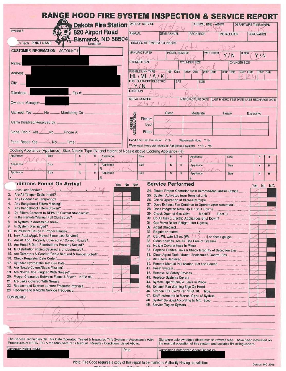
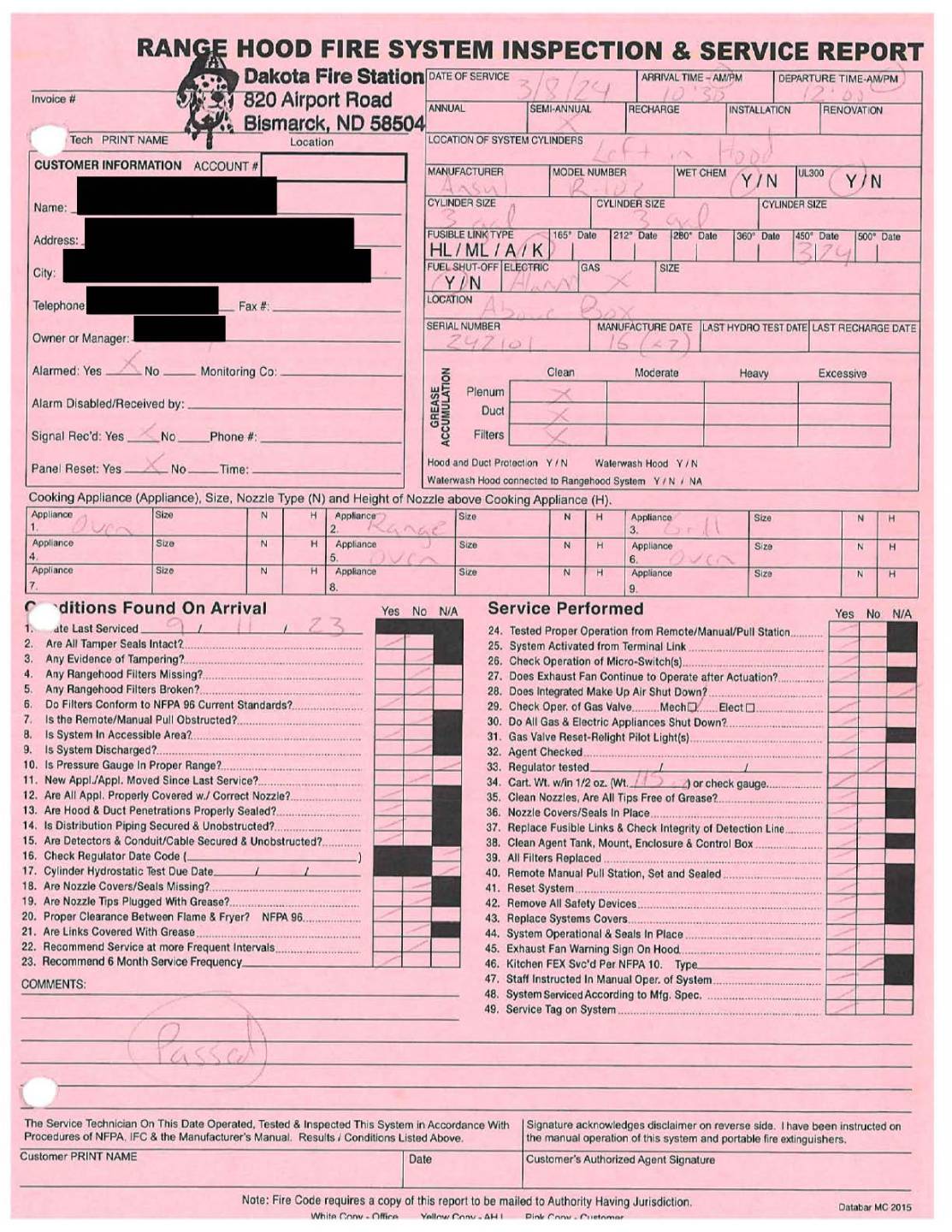
Range Hood Systems
- Inspection of UL300 Kitchen Range Hood:
- Monthly - Hoods shall be inspected per manufacturer’s listed installation and maintenance manual or the owner’s manual.
- Semiannually – The range hoods automatic extinguishing system must be serviced and inspected for cleaning.
- Records:
- The date of the inspection and the initials of the inspector shall be kept on record.
- Monthly Records shall be retained for the period between the semiannual maintenance inspections.
- Semiannual Records shall be retained for a period of 1 year after the next required maintenance and inspection for cleaning.
- Inspection Sheets: These are usually provided by the company doing the inspection.
- Wet Agent Fire Suppression System Inspection and Testing Report.
- Work Site #
- Name of facility
- Street Address
- City – State and zip code
- Authority Contact and phone number
- Date – Time in and time out
- Last maintenance date and performed the maintenance
- Manufacturer
- Type of Wet Agent
- Control/Release Data
- Expellant Gas Line
- Tank/Cylinder Data
- Nozzles
- Detection Data
- Remote Release Data
- Gas Valve Data
- Electrical Functions
- Notification/Annunciation
- Wet Agent Fire Suppression System Inspection and Testing Report.
- Inspection and Cleaning of Kitchen Exhaust Systems
- The extinguishing system is in its proper location.
- The manual actuators are unobstructed.
- The tamper indicators and seals are intact.
- The maintenance tag or certificate is in place.
- No obvious physical damage or condition exists that might prevent operation.
- The pressure gauge, if provided, shall be inspected physically or electronically to ensure it is in the operable range.
- The nozzle blow-off caps, where provided, are intact and undamaged.
- Neither the protected equipment nor the hazard has not been replaced, modified, or relocated.
- If any deficiencies are found, appropriate corrective action shall be taken immediately. At least monthly, the date the inspection is performed and the initials of the person performing the inspection shall be recorded. The records shall be retained for the period between the semiannual maintenance inspections.
- A K-type fire extinguisher is required in kitchens that are equipped with a UL 300 hood system. A sign must be installed instructing on the use of the extinguisher.